
A vapor recovery unit works on tank vapor near atmospheric pressure, which is where air gets in. An optical oxygen analyzer on the vapor line between the separator and the VRU compressor reads that air as it arrives, in ppm or percent, with no electrochemical cell to replace.
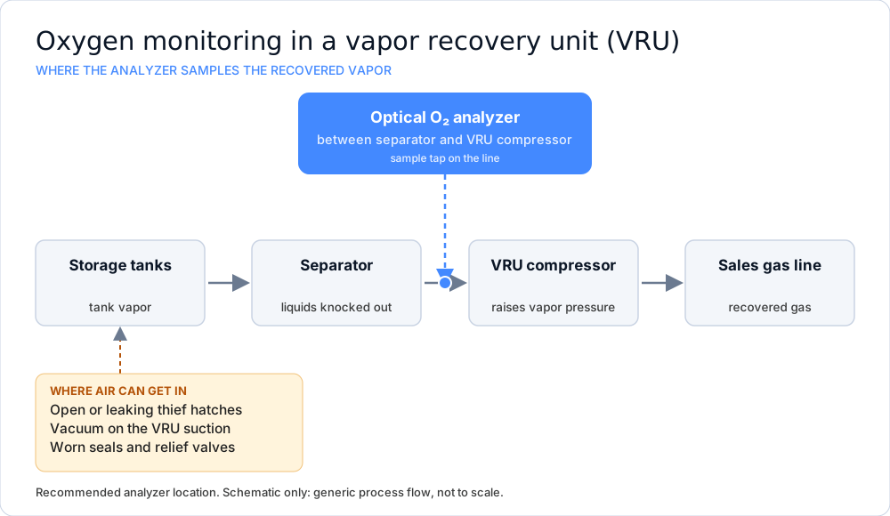
A VRU draws vapor from tanks at or near atmospheric pressure. If it pulls faster than the tanks make vapor, the vapor space can go slightly negative, and air enters through any open path: an unlatched thief hatch, a relief valve that has not reseated, a worn seal or a loose fitting. That air is about 21 % oxygen.
EPA's Natural Gas STAR guidance on installing VRUs on storage tanks describes the design answer: a control pilot that shuts the compressor down and lets vapor flow back into the tank, so a vacuum does not form when the oil level drops. An oxygen reading tells you when that protection was not enough.
The events are often brief. A hatch is open during a load-out, a tank cools overnight, or the compressor outruns the vapor supply for a few minutes. A grab sample captures one moment and can miss all of them. A continuous reading shows when it happens and how often.
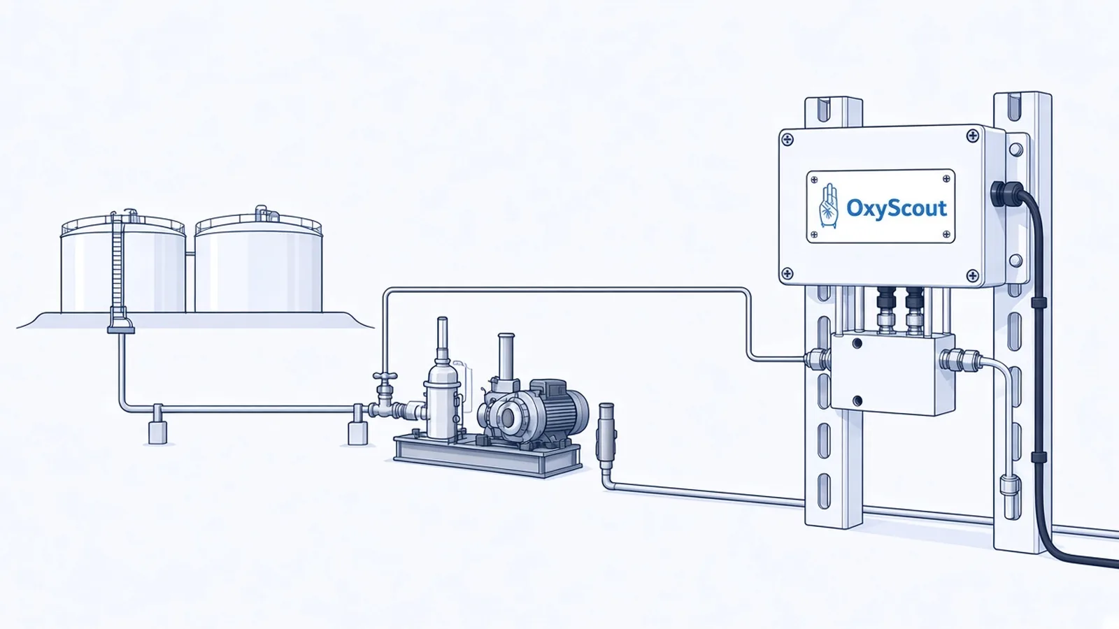
The analyzer mounts on the vapor line between the separator and the VRU compressor. That position puts it ahead of the compressor, so it reads the vapor before the vapor is compressed into the recovered gas, and it catches air before the air reaches the sales line.
The sample tap uses a 1/8 in tube compression fitting. The analyzer measures 9 × 7 × 2.5 in, weighs 4 lb, and runs on 9–36 VDC at 35 mA plus the current used by its analog outputs. The analyzer sends 4–20 mA or RS-485 Modbus RTU to your controller or SCADA. The optional sample system adds a pressure regulator and gauge, a secondary filter and a 3-way valve for calibration gas or process sample, and an optional flowmeter regulates vent flow to atmosphere if required.
Tank vapor is pulled at very low pressure, so moving sample through the analyzer needs a plan for each site.
Three patterns are worth separating. A short spike during loading or gauging can point to a hatch or a transfer event. A rise that repeats at the same time each night can point to temperature-driven contraction. A slow climb that stays up can point to a leak that stays open, such as a relief valve, a seal or a fitting. These are places to start looking. The analyzer reports oxygen, not the cause.
Tank vapor often carries H₂S and CO₂. OxyScout has no cross-sensitivity to them and no poisoning of the optical sensor, and there is no electrochemical cell to wear out. Typical response time is under 10 seconds.*
*Based on controlled lab conditions.
| Ranges | The Ultra-Trace range is 0–50 ppm, Trace range is 0–1000 ppm and the Percent ranges are 0–1 %, 0–10 % and 0–21 % by volume. |
|---|---|
| Detection limit* | The limit of detection is ≤ 0.5 ppm O₂ on the Ultra-Trace range (0–50 ppm), 50 ppm O₂ on the Trace range (0–1000 ppm), 0.01 %vol O₂ on the Percent 0–1 %vol range and 0.1 %vol O₂ on the Percent 0–10 % and 0–21 %vol ranges. |
| Accuracy* | Accuracy is ±2 ppm or ±5% of reading, whichever is greater, on the Ultra-Trace range (0–50 ppm). Accuracy is ±0.5% of full scale on the 0–1 %vol Percent range, and ±5% of full scale on the Trace range (0–1000 ppm) and the 0–10 % and 0–21 %vol ranges. |
| Response time* | Typical response time is under 10 seconds. |
| Pressure | Up to 250 PSI input pressure† |
| Outputs | The outputs are a 4–20 mA loop (current sink) and RS-485 Modbus RTU (2-wire half-duplex). |
| Power | The analyzer runs on 9–36 VDC and draws 35 mA plus the current used by its analog outputs. |
| Area classification | The analyzer is engineered for Class 1 Division 2 (Zone 2) hazardous areas. |
| Environment | Process and ambient temperature is 0 to 50 °C, the enclosure is IP67, and extreme-heat and extreme-cold enclosure options are available. |
*Based on controlled lab conditions.
†Without Flowmeter installed. Higher ratings if regulator installed upstream.
Air ingress on a VRU is often intermittent. A hatch, a temperature swing or a compressor pulling vacuum can start and stop between samples. A continuous analyzer shows the event when it happens, and the signal can drive an alarm.
Pick the range around your alarm point. The 0–50 ppm range suits low-ppm limits, and the percent ranges (0–1 %, 0–10 %, 0–21 %) suit watching larger air ingress.
The optional sample system includes a pressure regulator, a filter and a calibration valve, but moving sample through the analyzer at near-atmospheric pressure needs a plan for your site.
Yes. The analyzer has a 4–20 mA loop (current sink) and RS-485 Modbus RTU output, so it can feed a controller, RTU, PLC or SCADA system where you set your own alarm points.
No. The analyzer measures oxygen optically, so there is no electrochemical cell to replace.
Tell us the vapor pressure at the tap and the oxygen limit you care about. We will review the setup and send a quote.
Get a Quote